

Hello friends, Welcome to the another Electronics tutorial. In this tutorial, we will learn how to control any home appliances using TV Remote or any source of infrared wave. The IC which is used here is a Nand CD4017 IC. This IC uses a Infrared Sensor ( TSOP 1838) for detecting Infrared wave and this signal is interpreted by the chip and the chip uses this infrared signal for operating relay, connected at output. The relay is a electronic component which is almost like a switch. The only difference is that you can control the appliances in relay by supplying power whereas in switch you had to manually switch on and off. we will also look at at some basic techniques for controlling home appliances using relay and also make a example through which we will know how to control electronics appliances using TV Remote. So, let's begin....
Things Needed
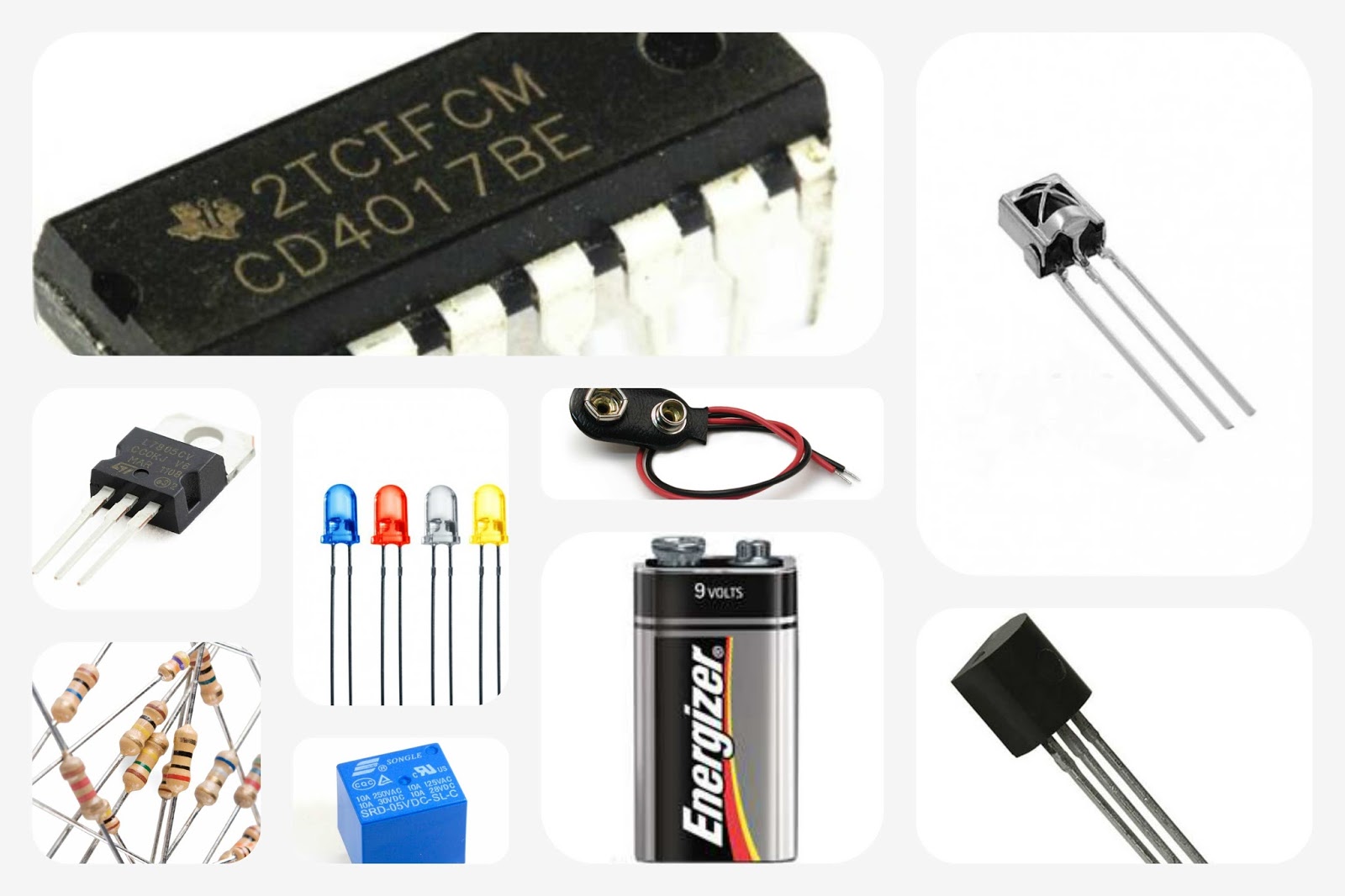
[Circuit Parts]
> CD4017 IC - 1 piece.
> Infrared Sensor (TSOP 1838) - 1 piece. (you can choose any Infrared Sensor. Only you had to know the pin configuration of infrared sensor that you are using.)
> Transistor. PNP transistor - 1 piece, NPN transistor - 1 piece. ( I used BC558 as PNP Transistor & BC547 as NPN Transistor.)
> 7805 Voltage Regulator IC - 1 piece.
> Resistor ( 100 ohm - 3 pieces, 100k ohm resistor - 1 piece. )
> LED - 1 piece. (You can use any color of led. The Led is optional because it is used only to indicate whether relay is on or off.)
> 5v PCB Relay - 1 piece.
> Perforated Board - 1 piece.
> 9v Battery - 1 piece.
> 9v Battery Cap - 1 piece.
> Some Wires.
[Miscellaneous Parts]
> Soldering Flux.
> Soldering Wire.
[Tools]
> Soldering Iron.
Circuit Diagram.

The Circuit Diagram looks very complicated, but once you understand it, you will find the circuit very simple. The main component or heart of this circuit is the CD4017 IC which controls almost all the function of this circuit. Now, let's understand the circuit from power supply to working. 9v Battery is used as a power source here in the circuit. The 9v is fed in the 7805 Voltage regulator IC and the output from voltage regulator is connected and supplied to the circuit. you can also use any 5v power source instead of 7805 voltage regulator IC. The connection of the battery with the 7805 IC is given below.
 |
| 7805 Voltage Regulator Circuit |
The 7805 IC is used here to convert the 9v to 5v for the proper working of the circuit. It's time for working of the Circuit. The Infrared sensor used here is used to detect infrared signals from TV Remote or any another Infrared Source. When the sensor receives any infrared signal, the output of sensor goes to high from low level and this high level is supplied to clk pin of CD4017 IC. The CD4017 IC when receives this signal, It bounces its output from Q0 to Q1 and the current stops supplying to the base of the transistor which powers the relay and this turns off the relay and also the outlet connected to relay. Again, when the signal is received/detected by sensor, the output bounces from Q1 to Q2 and this pin is connected to reset which resets the chip and the chip comes to the original state i.e. the state when it is turn on first time. and this process goes on every time and the outlet is controlled.
[Extras]
The circuit includes many more small components excluding the components above described. Now, let's know about these components, because these are also helping in the proper working of the circuit. The BC558 transistor is used here to amplify the signal received from the sensor to supply to the IC. The BC547 transistor is used here to act as a switch for the relay, because the output from the IC is not able to turn onoff the relay. The 100 ohm Resistor is used here to properly supply the required current to the components prevent it from being damaged. The 1N4007 diode is used to prevent the short circuit to relay when is is consistently turn on/off. The 100K ohm Resistor works as a load for the BC558 transistor. As we know, that in transistor to work properly every connection should be made properly. The collector pin of transistor is connected to any load, but when the resistor, here is not connected as a load to transistor, the current from the transistor will not flow to clk pin of CD4017 IC and the circuit will never work.
Constructing and Testing.
Hope this project will make you enjoy this weekend. If you have any problem/question regarding this project, then ask me in comment box. Thanks for Visiting and giving your valuable time for reading this project.


)
0 Comments