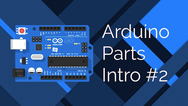
Hello friends, welcome to the another tutorial of How to Electro. In this tutorial, we will know about the main parts which help the arduino to work properly. We will totally cover 10 to 11 parts in this tutorial. By the end of this tutorial , we will get a clear information about the arduino working and parts uses. In this tutorial, we will know about the popular arduino board arduino uno, which is a easy to use board with less complicated electronics. This board will help us to understand of almost all the arduino boards, because the construction of all the boards is almost same. So friends, let's begin...
Arduino Parts
2. Power Jack - It is used to take input power from 9v-12 v Power supply to power the board and to work properly.
3. Voltage Regulator - It is used by arduino to regulate the voltage in 3.3 v and 5v according to the power needed by components.
4. 16Mhz Crystal - It is used as a timer in arduino. The arduino uses it as a oscillator which is used to calculate time interval and use it. Generally used oscillator in arduino is of 16 mhz frequency.
5. Reset - A pin which is used to rerun the program from start and is used by connecting to a push button, with one pin connected to ground.
6. 3.3V - It supply a output voltage of 3.3V.
7. 5V - It is used to supply output voltage of 5V.
8. GND - It is used to Ground the circuit i.e. to take negative power or to supply negative power.
9. Vin - It is used to supply input power to the board to work properly. It takes voltage range of 9V-12V.
10. Analog pin (A0 to A5) - The analog pin is used by arduino as a input pin which receives some input from the sensor as from light sensor, sound sensor and so on.
11. Microcontroller - It is the main brain of the arduino, which contains all the code ,which is interpreted by arduino to work as described. The most common microcontroller used is the Atmega328P chip produced by Atmel Company.
12. ICSP Pin - It is used to connect two arduino or to program the arduino. it can be used as a extension to join the arduino board's. it totally has 6 pins each for desired purpose. We will know about these in the further tutorials.
13. On LED - It indicates whether the board is properly powered or not. it glows when the power is properly provided to the board.
14. TX & RX LEDs - It indicates the data transfer between arduiNo and some other thing. The TX indicates the transmission of data and blink in the baud rate as specified and RX indicates whether the data is received to the arduino and it also blinks in the same baud rate of received data.
15. Digital Pin ( D0 to D13) - it is used to take digital inputs and give digital outputs. We will understand more of this in the next tutorial. The 0 and 1 pin is used as a pin which is used to transfer and receive data between arduino and another components.
16. AREF - It is used as to provide power to the components connected to Analog pins. it takes a range of voltage of 0V - 5V. when power is supplied to the AREF, the power to the analog pin is supplied from AREF Pin POwer not from the arduino internal voltage regulator.
17. Reset - It is used to reset the code i.e. to restart the program from the start.


0 Comments