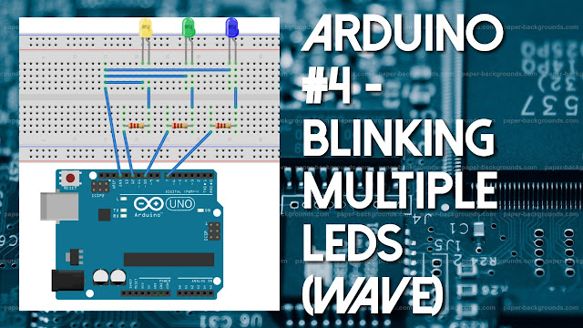
Hello friends, welcome to the another tutorial of How to Electro. In this tutorial, we will know about, how to blink multiple LEDs using Arduino. We will get clear explanation of the working of the circuit along with the code, which works to blink multiple LEDs, by the end of this tutorial. So friends, let's begin...
Blink (Multiple LEDs)
Blink LED actually means that the led will remain on for certain time and off for the previous certain time continuously, which causes blink effect in led. We can easily understand it with the help of our eyelids, which closes and open after certain time continuously, hence known as blinking of an eye. Now let's start with the circuit of the blinking of Multiple LEDs.Circuit
The Circuit is very simple of this arduino project. It only contains a few parts, wHich is easily available, and we can easily understand every components. It consists of 3 LEDs ( a I will only blink 3 LEDs here, you can add as much LED you like ), 3 100/200 ohm resistor ( number of LEDs is same as of the number of LEDs ) and some wires. We will know about the use of resistor which is used here, in the next tutorial. All the Ground Pin/ Negative Pin of LEDs are joined together, and is connected to the GND pin on the arduino with the help of a wire, wHich supplies negative power to the Led. Now it only requires +5V ro glow, and we use this property to blink it, by setting timer in the arduino code. All the Positive Pin of the LEDs are connected respectively to one 100/200 ohm resistor. Here we can use any of the 100 ohm or 200 ohm resistor. And another pin of the resistor, which is left, is connected to the arduino digital Pin 7,10 and 12. These pins are connected to the arduino, so that after regular interval, it will supply +5V to the Led, wHich turn on the LED, hence creating a blinking LED. So friends, that's all of the circuit of the blinking led. Now let's know about the code of the arduino, also known as sketch in arduino language.
Code
int Led1 = 7;
int Led2 = 10;
int Led3 = 12;
void setup(){
pinMode(Led1,OUTPUT);
pinMode(Led2,OUTPUT);
pinMode(Led3,OUTPUT);
}
void loop(){
digitalWrite(Led1,HIGH);
digitalWrite(Led2,LOW);
digitalWrite(Led3,LOW);
delay(500);
digitalWrite(Led1,LOW);
digitalWrite(Led2,HIGH);
digitalWrite(Led3,LOW);
delay(500);
digitalWrite(Led1,LOW);
digitalWrite(Led2,LOW);
digitalWrite(Led3,HIGH);
delay(500);
}
Above is the code of the arduino which will help to blink multiple led with a regular interval of 500ms (1 Second = 1000ms), creating a wave effect between the LEDs. In the first three line of codes, three variables are initialized, with unique names and some values. All the variables are of integer type, which stores integer values in it. These variables are initialized to use it within the code at anytime, anywhere with the unique name. The structure of variables consists of the type of variable, unique name and the value. Type of variables depends on the value that you want to store, unique name means any name which can be easily recognized by you or any name you want, which is already not initialized in the code, and the value is the value you want to store. More information About variables is given in the previous tutorial.
After variables, the mode of the pin is set in the setup() function, which runs only one time, when the arduino is powered on, or reset button is pressed. The pin mode means that the pin is working either as an Input pin, which takes some value from sensor, or, output pin, which gives some value as output. In the above code, we are driving a LED using Arduino, so all the pins are declared as output. pinMode() is a function, which takes two value as its parameter, one is pin number and another is the mode Either Input or Output. So above code, contains Ouput as its second parameter.
Now it's time for loop() function, which runs consecutively, and is responsible for the blinking of LEDs. In the loop() function, digitalWrite() function is used, which takes two parameters, one is the digital pin number, and other is the value either HIGH or LOW. HIGH means that it will supply +5V to the digital pin number which is specified in the first parameter of the function, and LOW means that, it will supply 0V to the digital pin number, which is taken as the first parameter of the function.
In the first three line of the loop() function, the digitalWrite() function supplies +5V to the Led1 and 0V to Led2 and Led3. This causes the first led to turn on and other LEDs to remain off. After this delay() function is used, which adds delay as specified in ms (milliseconds) before the execution of the next line of code. When the delay ends, the next line of code will be executed by arduino, wHich turns on the second led and turns off first and third led. and again after the delay specified, the third led will turn on and turns off the first and second led. At the last line of code, again a delay is added, which pauses the loop function to reexecute for 500ms and after the delay, this function goes on and on forever, till the board is powered on. Hence creating multiple led blink with wave style.
So friends, that's all for this tutorial. Hope u enjoyed it. If u have any problem, then ask me in comment box. I will try my best to answer the question as soon as possible.
Thanks -
How to Electro ( Samridh Sharma )


0 Comments